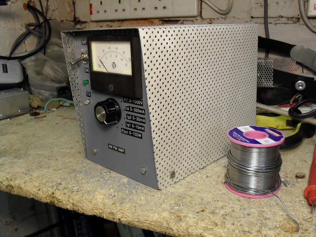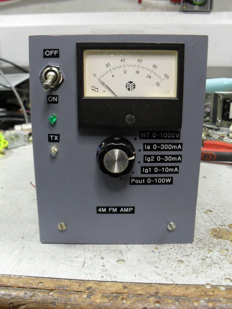

This 4m FM push pull power amplifier is designed to run with the Tait T525 4m conversion shown elsewhere on this site. Although this is old technology, i think it still has a place in the misers shack ( mine ). With approximately 4 Watts of drive from the T525 this amplifier will produce 100 watts output all day long. Nearly all of the parts are liberated from a Pye T30AM / FM or similar base station transmitter, I picked up three of these for a total of £15.00 ( a fiver each ) at a rally a few years ago, they are usually cheap as nobody wants them. Most base stations using a QQV06-40A for the final will be suitable for parts, the band type ( VHF high, mid or low ) type is not important as the tank coils can be rewound if necessary, also the modulation type ( AM or FM ) does not matter.
The photographs show the construction method, no expense has been spared, for the chassis a diecast box is used. The case walls are made from some old paxolin copper clad board and a perforated aluminium ceiling tile. The original PA cage screen is cut down and re-used. It is important to note that the QQV06-40A should be mounted slightly recessed below the chassis so the internal base screen is level with the chassis otherwise instability can occur. A small PC fan cools the valve during TX periods, this can be omitted but the output power will have to be reduced if long overs are used. During RX periods the fan runs at just under half speed so very little noise is produced but during TX periods it runs at full tilt. The circuit is very simple, RF output from T525 is coupled to the control grids of QQV06-40A via T1. The secondary of T1 is center tapped, negative bias is introduced at this point. The neccessary 180 degrees phase shift for the control grids is provided by VC1 being center tapped and grounded at RF, T1 is also tuned by VC1. During RX periods the G2 supply is removed by RLY2, thus the valve is completely cut off during RX periods. A low pass filter follows the tuned anode tank circuit, do not omit this otherwise harmonics will be radiated into the upper VHF band. Metering is provided for anode current, screen grid current and control grid current, this was modified later to also provide HT and relative power out. The relay switching circuit ensures correct sequence of relay activation / deactivation. For 124 Watts output the anode current is 220 mA, screen current is 12mA and control grid current is 6mA. As this amplifier is biased for class C it is not suitable for linear use unless the bias is altered accordingly and a regulated screen supply is used ( I have not tried this as I do not have a source of 4m SSB ). The power supply is a separate unit and again uses the parts from the base station. The original power supply transformer has taps for various secondary HT voltages, 600V was used in the base station, 800V is used here. DC to the HT smoothing reservoirs is only applied during TX periods ( as is done in the original base station ) this will prolong the life of the smoothing capacitors, it is up to you if you choose to do the same. The on / off switch on the amplifier switches heater voltage and ancillary 12 VDC, in the off position the radio can run as normal without the amplifier. When the switch is on, the amplifier is active, NOTE; although the amplifier is not active in the off position there is still HT 800VDC and G2 supply present in the amplifier chassis - beware!
The power supply uses most of the parts from the original base station and the circuit is virtually identical to the original, just a few subtle differences: a LM7812 is used as a 12 Volt regulator, the HT switching relay is activated by grounding the cold end of its coil and finally the valve heater supply uses a diode / resistor dropper - this does give asymmetrical loading on the transformer heater winding but this is of no consequence here and it is more efficient than using a series resistor. The heater winding produces 25VAC, the QQV06-40A requires 12.6 VAC so hence the dropper. Three output supply sockets are fitted, this is so three amplifiers ( 6m, 4m and 2m ) can be run from the same PSU although not at the same time. The PSU uses half of the original chassis, it could be made much smaller but I did not bother.
The last photograph shows the amp running with a Bird meter in line with the output, it is on the 150W scale and as you can see the output reads approx 108W ( once the correction factor is taken into account for this particular Bird meter - X1.15 @ 70MHz, the true ouput is 124W ). I left the amp keyed at this power for 8 minutes with no ill effect, every thing ran cool - the fan and the relatively low frequency of operation for this valve contribute to this greatly. For 100W output simply reduce the drive from the transceiver.
Barry Zarucki M0DGQ
HOME